0


The VE-Bus BMS (Battery Management System) protects LFP (Lithium Iron Phosphate) batteries from overvoltage, undervoltage and overheating.
Each individual cell of a LiFePO4 battery must be protected against overvoltage, undervoltage and overheating.
Victron LiFePO4 batteries feature load balancing, temperature and voltage control (acronym: BTV) and connect to the VE.Bus BMS with two sets of M8 circular conductors.
BTVs for several batteries can be connected in series. Up to 10 batteries can be installed in parallel, and up to 4 batteries can be connected in series (BTVs are easily connected in series), so that a 48 V battery bank of up to 2000 Ah can be assembled. Please refer to the LiFePO4 battery documentation for further details.
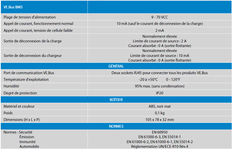
BMS operating voltage range: 9 to 70 V DC.
The VE.Bus BMS connects to MultiPlus, Quattro or Phoenix converters with a standard RJ45 UTP cable. Other products without VE.Bus can be controlled as shown in the attached files.
The load disconnect output is normally high, and becomes floating in the event of imminent cell undervoltage. Maximum current: 2 A.
Output with charger (or alternator) disconnection is normally high, and becomes floating in the event of imminent cell overvoltage or overheating. Maximum current: 10 mA.